moddbox
New Member
Ok. So there are alot of great "how to" guides on here... but I haven't seen a complete and thorough "how to" supercharger install for the 4.0L SOHC engine (specifically for Ford Ranger/2dr Explorer/Sport Trac & B4000). Also, sorry for the 4 posts... this blog limits posts to 10000 characters per post)
So... here it goes. If you obtain a Moddbox Installation kit and any Eaton M90 supercharger (89-95 either style inlet), follow the following instructions and you're good to go. No tune required. 100% bolt-on mod. You can get your installation kit here:
ModdBoxModdBox - Engineering your driving experience @
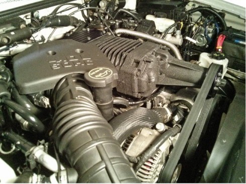
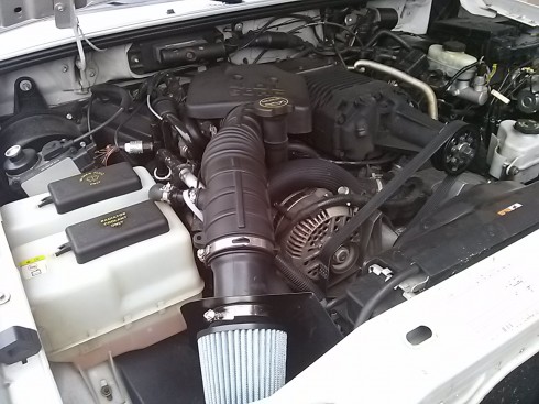
I've also decided to post the "final result" first. If you like it.. proceed to read the "how to".
Here's a road test of the 3.5 psi pulley equipped with no cooling equipment installed.
[ame="http://www.youtube.com/watch?v=Fa6iC_lzK6Q"]TESTDRIVE[/ame]
Here's the Dyno. 215 hp & 237 lbft at the rear wheels.
[ame="http://www.youtube.com/watch?v=O2xxu09nlO8"]DYNO[/ame]
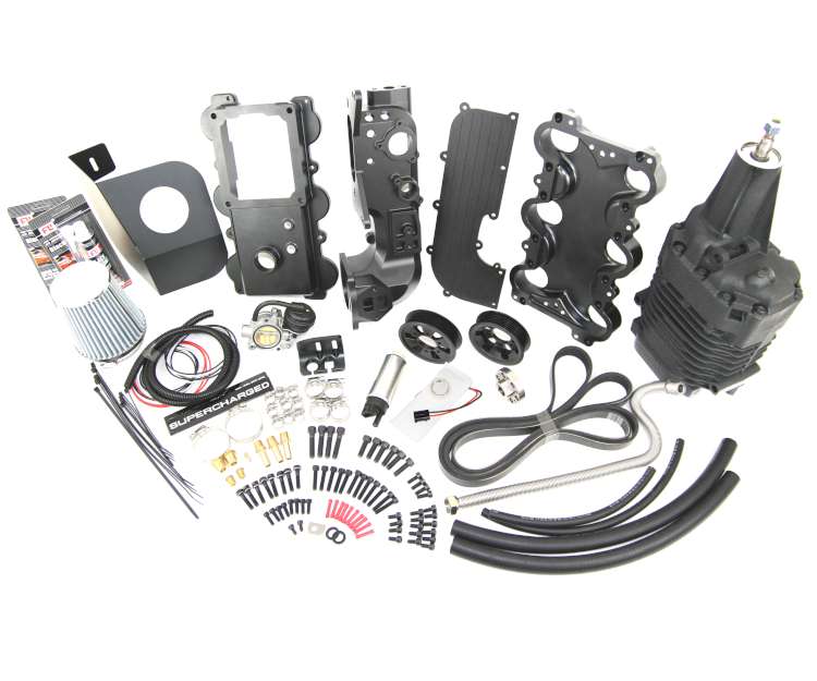
Kit Photo:
Installed Photos:
TOOLS REQUIRED
Tools Required:
Standard metric socket set
Needle Nose Pliers
T-30 Torx Bit
Fluid Funnel
Flat Head Screw Driver
Punch
...will add more soon
STOCK REFERENCE DIAGRAMS
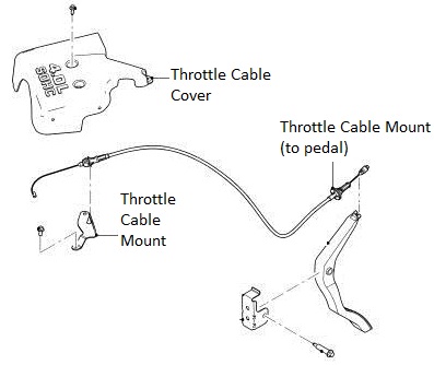
Stock Throttle Cable Reference Diagram
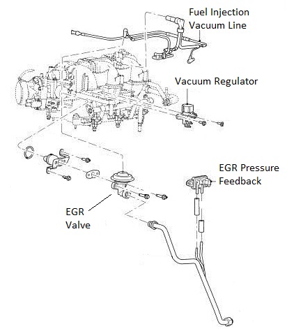
Stock EGR System Reference Diagram
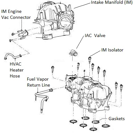
Stock Intake Manifold Reference Diagram
Stock Air Box Reference Diagram

Stock Throttle Reference Diagram

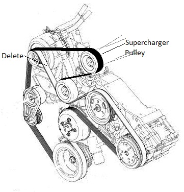
Belt Diagram Reference Diagram (Dark Belt Showing the ModdBox Orientation)

MODDBOX SUPERCHARGER KIT PARTS
ModdBox Supercharger Bypass Valve
http://modd.me/wp-content/uploads/2013/09/CAM04401.jpg
ModdBox 255lph Fuel Pump
http://modd.me/wp-content/uploads/2013/11/Moddbox255lph.jpg
ModdBox Heat Shield
http://modd.me/wp-content/uploads/2013/11/heatShield.jpg
ModdBox 70mm Air Filter
http://modd.me/wp-content/uploads/2013/11/GreyAirFilter.jpg
ModdBox Throttle Cable and Cruise Control Mount
http://modd.me/wp-content/uploads/2013/11/4LV6CologneInstall-7.jpg
ModdBox 3.0 & 3.5 psi Supercharger Pulleys
http://modd.me/wp-content/uploads/2013/11/CAM04371.jpg
ModdBox Supercharger Pulley Quick Adapter
http://modd.me/wp-content/uploads/2013/11/AdapterPully.jpg
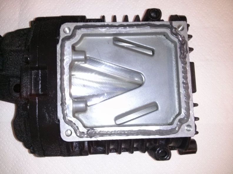
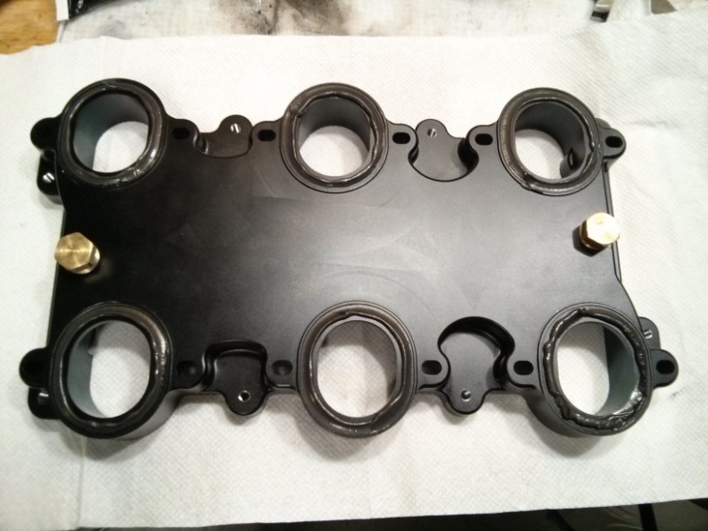
ModdBox Plenum Bottom Plate
http://modd.me/wp-content/uploads/2013/11/4LV6CologneInstall-9.jpg
ModdBox Plenum Top Plate
http://modd.me/wp-content/uploads/2013/11/4LV6CologneInstall-10.jpg
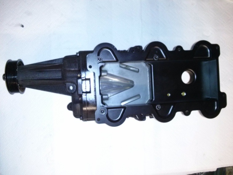
ModdBox Intake Manifold
http://modd.me/wp-content/uploads/2013/11/4LV6CologneInstall-11.jpg
ModdBox Intake Manifold Top
http://modd.me/wp-content/uploads/2013/11/4LV6CologneInstall-12.jpg
ModdBox M22-1.5mm EGR Extension
http://modd.me/wp-content/uploads/2013/11/CAM04413.jpg
Black Silicone Liquid Gasket
http://modd.me/wp-content/uploads/2013/11/CAM04389.jpg
6pk Serpentine Belt
http://modd.me/wp-content/uploads/2013/11/6pkBelt.jpg
1/4" Electrical Loom
16 ga wire & connections
Heater Hose
Fuel Hose
Hardware and Fittings
INSTALLATION STEPS
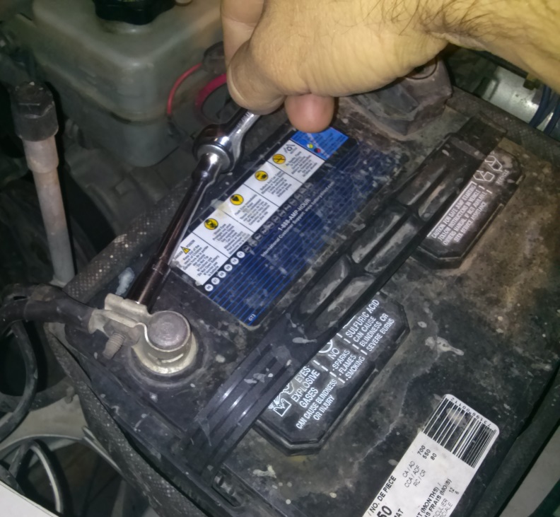
Remove the negative battery cable (1 bolt). Secure it to the side of the battery to prevent any accidental contact with the negative terminal.
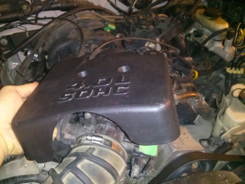
Remove the Throttle Body Cover (2 bolts). If your model is equipped with a second Crank Case Ventilation hose, you will be required to remove the hose clips on the side of the Throttle Body Cover (not shown here).
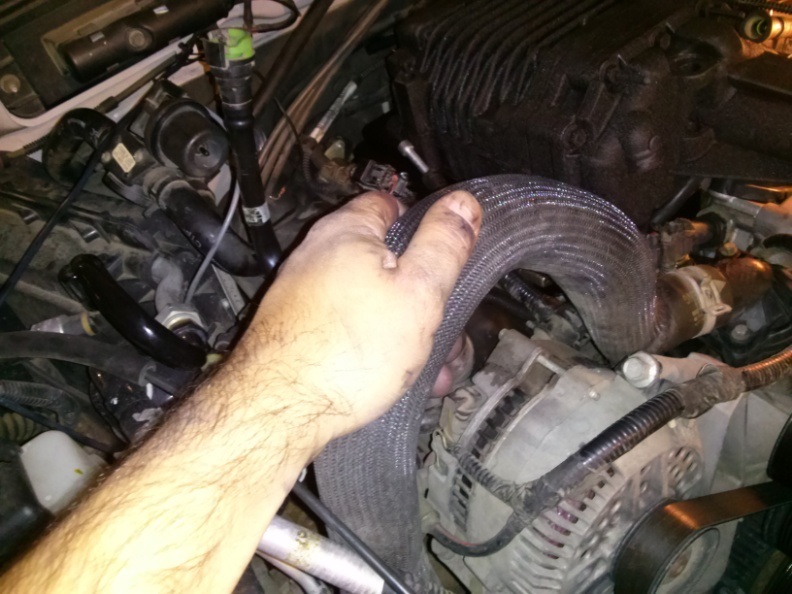
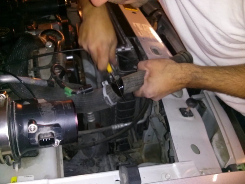
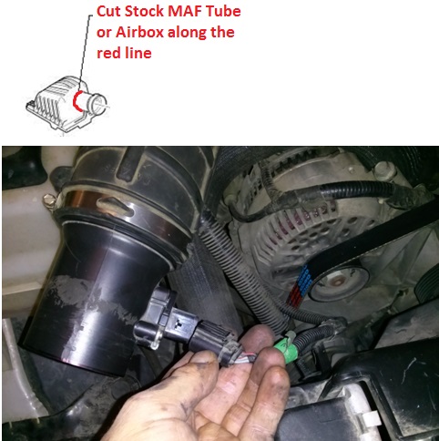
Loosen the hose clamp and disconnect the Intake Tube from the Stock Air Box Assembly.

Loosen the hose clamp and disconnect the Intake Tube from the Throttle Body.

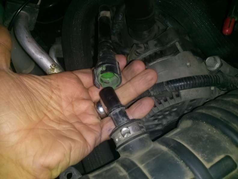
Disconnect the Crank Case Vent Hose(s) and remove the Intake Tube. Set the Intake Tube aside for later use. Some models have a second Crank Case Vent Hose. For more information, see the Stock Setup Diagrams provided at the beginning of this instruction manual.
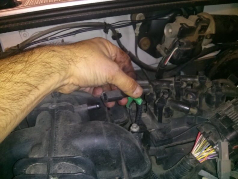
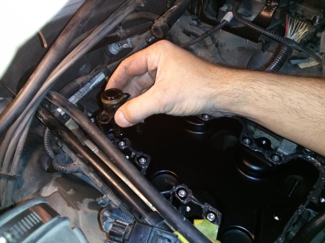
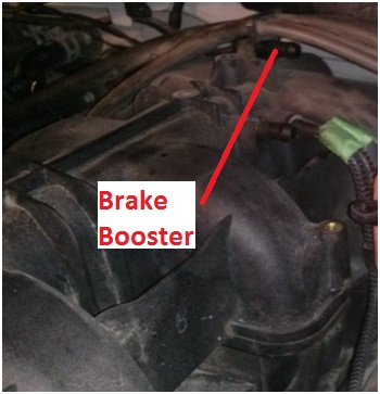
Remove the Brake Booster Line from the back of the Intake Manifold. Tape and label if necessary.
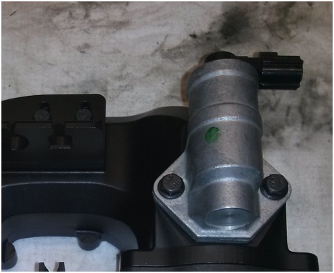
Unplug the cable connected to the IAC Valve.

Unbolt and remove the IAC Valve (2 bolts). Set the IAC Valve aside for later use.

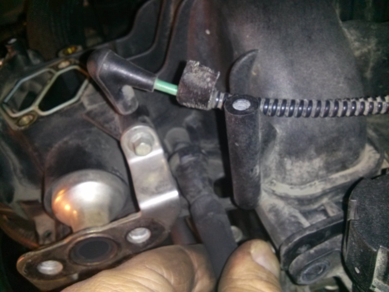
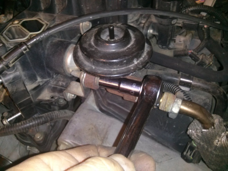
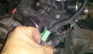
Unplug the Vac line connected to the EGR. Tape and label the Vac Line if necessary.

Unbolt the EGR Valve (2 – 12mm bolts).

Remove EGR Valve by disconnecting the EGR Tube. Set the EGR Valve aside for later use.
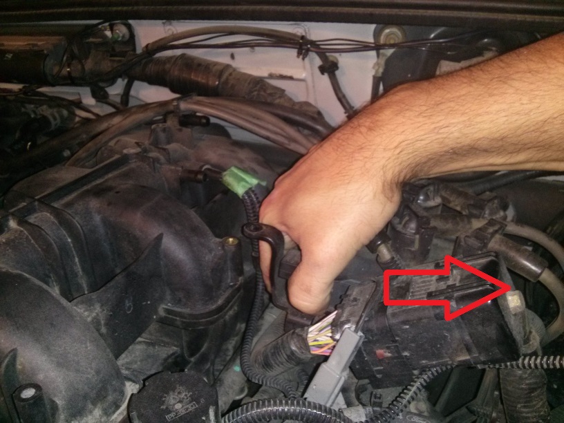
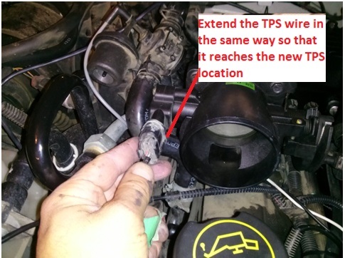
Unplug the TPS Sensor. Tape and label the plug if necessary.
Remove the Throttle Cable from the Throttle Body Valve. The cable can be slipped free by manually actuating the valve 90 degrees and providing slack in the cable.

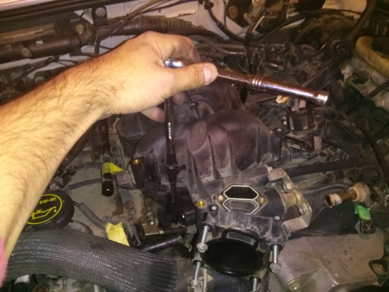
Unbolt the Throttle Body Valve (4 bolts). Set the Throttle Body Valve aside for later use.

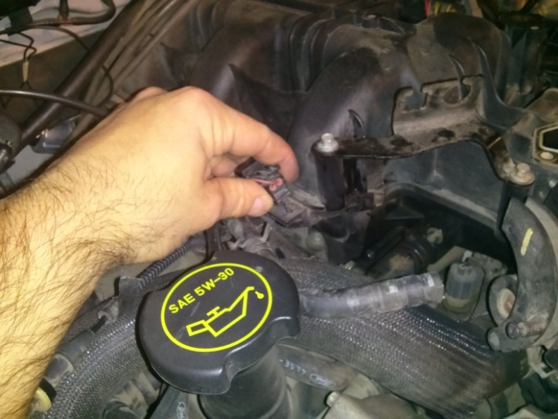
Disconnect the Throttle Cable and the Cruise Control Cable.

Disconnect the electrical wire mount from the left side of the Intake Manifold.
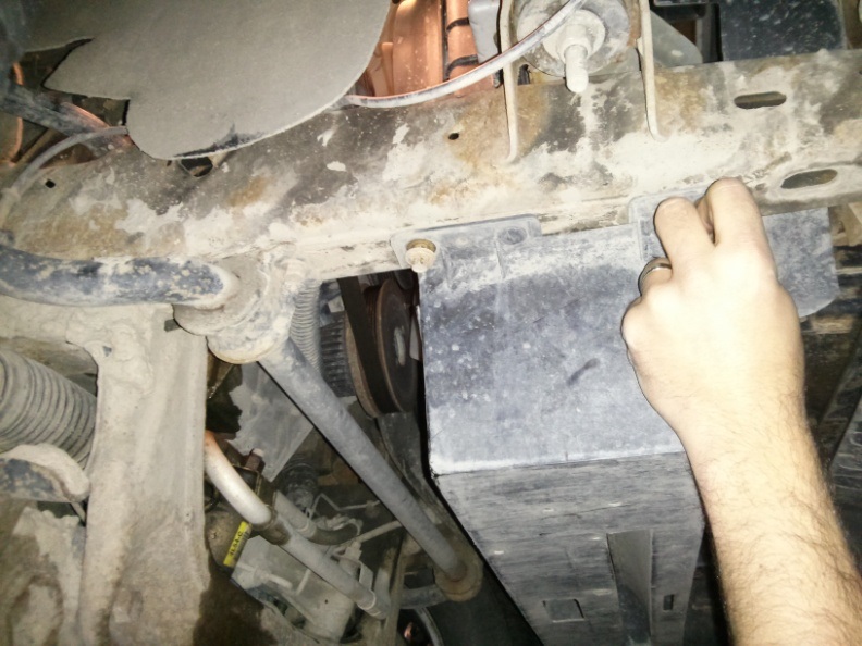
Locate the plastic Radiator Rock Shield located underneath the engine bay. Remove the bolts and set it aside.
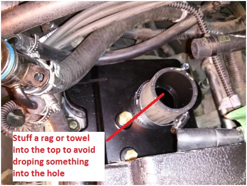
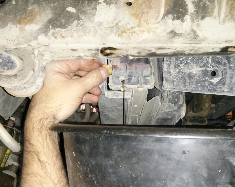
Locate the plastic Radiator Drain Valve at the bottom passenger side of the Radiator. Turn this plug and release only approximately a 3/4 gallon of coolant fluid (~3L). This is to allow the removal and relocation of coolant lines in the proceeding steps.
... see part 2 of 4 (limit to 10000 characters)
So... here it goes. If you obtain a Moddbox Installation kit and any Eaton M90 supercharger (89-95 either style inlet), follow the following instructions and you're good to go. No tune required. 100% bolt-on mod. You can get your installation kit here:
ModdBoxModdBox - Engineering your driving experience @
I've also decided to post the "final result" first. If you like it.. proceed to read the "how to".
Here's a road test of the 3.5 psi pulley equipped with no cooling equipment installed.
[ame="http://www.youtube.com/watch?v=Fa6iC_lzK6Q"]TESTDRIVE[/ame]
Here's the Dyno. 215 hp & 237 lbft at the rear wheels.
[ame="http://www.youtube.com/watch?v=O2xxu09nlO8"]DYNO[/ame]
Kit Photo:
Installed Photos:
TOOLS REQUIRED
Tools Required:
Standard metric socket set
Needle Nose Pliers
T-30 Torx Bit
Fluid Funnel
Flat Head Screw Driver
Punch
...will add more soon
STOCK REFERENCE DIAGRAMS
Stock Throttle Cable Reference Diagram
Stock EGR System Reference Diagram
Stock Intake Manifold Reference Diagram
Stock Air Box Reference Diagram
Stock Throttle Reference Diagram
Belt Diagram Reference Diagram (Dark Belt Showing the ModdBox Orientation)
MODDBOX SUPERCHARGER KIT PARTS
ModdBox Supercharger Bypass Valve
http://modd.me/wp-content/uploads/2013/09/CAM04401.jpg
ModdBox 255lph Fuel Pump
http://modd.me/wp-content/uploads/2013/11/Moddbox255lph.jpg
ModdBox Heat Shield
http://modd.me/wp-content/uploads/2013/11/heatShield.jpg
ModdBox 70mm Air Filter
http://modd.me/wp-content/uploads/2013/11/GreyAirFilter.jpg
ModdBox Throttle Cable and Cruise Control Mount
http://modd.me/wp-content/uploads/2013/11/4LV6CologneInstall-7.jpg
ModdBox 3.0 & 3.5 psi Supercharger Pulleys
http://modd.me/wp-content/uploads/2013/11/CAM04371.jpg
ModdBox Supercharger Pulley Quick Adapter
http://modd.me/wp-content/uploads/2013/11/AdapterPully.jpg
ModdBox Plenum Bottom Plate
http://modd.me/wp-content/uploads/2013/11/4LV6CologneInstall-9.jpg
ModdBox Plenum Top Plate
http://modd.me/wp-content/uploads/2013/11/4LV6CologneInstall-10.jpg
ModdBox Intake Manifold
http://modd.me/wp-content/uploads/2013/11/4LV6CologneInstall-11.jpg
ModdBox Intake Manifold Top
http://modd.me/wp-content/uploads/2013/11/4LV6CologneInstall-12.jpg
ModdBox M22-1.5mm EGR Extension
http://modd.me/wp-content/uploads/2013/11/CAM04413.jpg
Black Silicone Liquid Gasket
http://modd.me/wp-content/uploads/2013/11/CAM04389.jpg
6pk Serpentine Belt
http://modd.me/wp-content/uploads/2013/11/6pkBelt.jpg
1/4" Electrical Loom
16 ga wire & connections
Heater Hose
Fuel Hose
Hardware and Fittings
INSTALLATION STEPS
Remove the negative battery cable (1 bolt). Secure it to the side of the battery to prevent any accidental contact with the negative terminal.
Remove the Throttle Body Cover (2 bolts). If your model is equipped with a second Crank Case Ventilation hose, you will be required to remove the hose clips on the side of the Throttle Body Cover (not shown here).
Loosen the hose clamp and disconnect the Intake Tube from the Stock Air Box Assembly.
Loosen the hose clamp and disconnect the Intake Tube from the Throttle Body.
Disconnect the Crank Case Vent Hose(s) and remove the Intake Tube. Set the Intake Tube aside for later use. Some models have a second Crank Case Vent Hose. For more information, see the Stock Setup Diagrams provided at the beginning of this instruction manual.
Remove the Brake Booster Line from the back of the Intake Manifold. Tape and label if necessary.
Unplug the cable connected to the IAC Valve.
Unbolt and remove the IAC Valve (2 bolts). Set the IAC Valve aside for later use.
Unplug the Vac line connected to the EGR. Tape and label the Vac Line if necessary.
Unbolt the EGR Valve (2 – 12mm bolts).
Remove EGR Valve by disconnecting the EGR Tube. Set the EGR Valve aside for later use.
Unplug the TPS Sensor. Tape and label the plug if necessary.
Remove the Throttle Cable from the Throttle Body Valve. The cable can be slipped free by manually actuating the valve 90 degrees and providing slack in the cable.
Unbolt the Throttle Body Valve (4 bolts). Set the Throttle Body Valve aside for later use.
Disconnect the Throttle Cable and the Cruise Control Cable.
Disconnect the electrical wire mount from the left side of the Intake Manifold.
Locate the plastic Radiator Rock Shield located underneath the engine bay. Remove the bolts and set it aside.
Locate the plastic Radiator Drain Valve at the bottom passenger side of the Radiator. Turn this plug and release only approximately a 3/4 gallon of coolant fluid (~3L). This is to allow the removal and relocation of coolant lines in the proceeding steps.
... see part 2 of 4 (limit to 10000 characters)